Wednesday, February 20, 2019

My First Track Day

In 2015 I experienced some of the best moments in my life.  As a senior in college, I had experienced a lot of social events that really defined me and helped me grow.  I made friends and learned lessons and along the way, I got hooked on cars.

Take a look at my first track day during that year and some of the things I experienced as a novice.  This was originally written in 2015:


On April 15th, I experienced my first track day ever thanks to SCCA and their new program called "Track Night in America."


Track Night in America is aimed at newcomers who wish to enter into track racing from essentially any avenue.  Whether you're a kart racer, autocrosser, or traffic jam bum, if you want to get to racing then you can do so with Track Night in America thanks to the SCCA.  It is a safe, controlled environment where you can push the limits of your car.  

As a matter of fact, everyone I was driving with either autocrossed before or was a regular autocrosser!

Image from SCCA

With a price tag of $150 before a one day only $25 discount, I could not resist the temptation.  Although the track day occurred from 3 to 9 PM, cutting into the work day, so-to-speak, this price is nearly half the cost of an average track day with HPDE or Hooked on Driving or any other camp.  However, with any event comes preparation that needs to take place.

As mentioned in my previous article, one of the first things I tackled was the brake pad situation.  On the track, stopping and turning are much more important than going straight.  One of the first things mentioned on New Jersey Motorsports Park's tech form is that brake pads should have more than one half of their life left.  


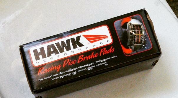
Since I had been using my HP Plus pads for more than a season of autocross, I felt it was time to finally replace them.  Here's what the old pads looked like-- they definitely have some life left in them!


Next, I sent my car off to my good friend Alex who was supposed to align my car.  The desired settings were:

Front camber: -3.0 degrees
Rear camber: -2.0 degrees
Front and rear toe: Neutral
Caster: non-adjustable on the RSX

However, thanks to a seized rear eccentric bolt, rear toe was not adjustable.  Since Alex didn't want to do a half-good job of aligning my car, he stopped at rear camber and let me know that after four hours he was unable to do anything with the car.  Thanks anyway Alex!


In addition to my poor alignment, out of good will, while Alex was washing my car, my aero block-off plates came off!  I guess it's better it happened there than at the track!


So, not only was my alignment bad and my block-off plates had popped off, but there was a slew of other things I had to comb over before I brought the car on the track.  On the checklist I had:
  • Fix front camber on driveway
  • Fix front toe on driveway
  • Make sure all bumper clips were securely fastened
  • Tighten down the battery strap
  • Install my new Hawks and bed them in
  • And make sure all suspension components were in good order.
I started by jacking the car up and maxing out the camber, within reason, on my adjustable top hats.  The top hats are pictured below:


However once I did that, the car's toe was EXTREMELY out of whack.  The car tracked hard to the right, so I had to adjust the tie-rod ends with some guesswork.

After doing that I tightened down the battery strap, I tightened the lower locking collars on my coilovers, I checked all of the wheel bearings, I installed my pads, and I bedded them in.  Since I had done so much in just a couple of hours before I was due to leave, I took it easy on my way to New Jersey Motorsports Park (NJMP).

When I got there, I signed in at the gate, drove to Thunderbolt (one of two circuits at NJMP) and got set up at the paddock area.


I brought a couple of things with me to make sure I'd be able to lounge comfortably during the advanced and intermediate sessions, my friend's GoPro, and I also brought some tools with me to make sure the car would be in good hands.

This is, of course, in addition to my helmet, which you must have, my long-sleeve sweater, which you must have, my close-toe shoes, which you must have, and my long pants, which you also must have.


Here's a more detailed list of what I brought:
  • A large tarp to cover my belongings
  • A box of open-ended wrenches
  • 10 mm through 14 mm deep sockets and a ratchet
  • A small toolkit which was comprised of a small ratchet and multiple shallow sockets
  • Allen wrenches
  • A chair
  • Dinner (PB&J)
  • Lots of water
  • GoPro
  • GoPro charger
  • Number plates-- in case we needed to be marked
  • Painters tape-- to hold my magnetic number plates to the car
  • A pen and some paper
  • Sunscreen
  • Helmet
  • Sweater
  • Jack stand
Note that I may have over-packed, but it was my first track day and I did not want to be unprepared.

Once set up, we held a driver's meeting.  During the driver's meeting we went over hand-signals to let people know that you want them to pass you, we went over passing zones, we went over flag signals, and we went over general tips to stay safe on the track.  The novice group had their own special leader who took the time to ensure we all had a fun, safe time on the track.  His name was Tom.  Thanks Tom!


After the driver's meeting, we filled out a self-tech form.  This form goes over everything from having your battery tied down, to discolored, cracked, or warped brake rotors, to no floor mats or loose items in the car.  We signed it to ensure that we were liable for any accidents and handed it over to the coordinators of the event.

Then, we headed out for paced laps to understand the corners on the track, including turn-in points, apex points, exit points, braking points, acceleration zones, and passing zones.  Here's the car that I was following-- an intermediate class STi!


After the paced laps, we sat and waited for the advanced driver (there was only one) to finish his run.  However, due to a stroke of bad luck, his drain plug came loose and he spilled some oil on the track.  According to my sources though, he was able to turn off the motor in time before damaging it!!  I'm happy to hear that.


As a result, there was a bunch of kitty litter put out on the track to make sure that no one slid on the oil.  This made for some tricky situations on its own, but it was definitely better than the greasy alternative, if you know what I mean.


After the mishap in the advanced group, we all waited for the intermediate group to get finished with their runs.  While we waited, I got some cool videos of the faster guys driving by!


And finally it was time for the beginner group to run.  Here's a map of Thunderbolt and the layout we ran for future reference:


Initially I took it slow.  I wanted to get a feel for the track and ramp up my corner speeds and get later and later in my braking zones to push the car.

Eventually I got comfortable on the track and really learned where I could push the car.  The turns that were covered in kitty litter initially tripped me up really bad.  And after the long front straight that leads into Turn 1 at NJMP, I learned that it was difficult to heel-toe due to the sheer magnitude of braking that needed to be done.

This area proved difficult to heel-toe downshift in


I wasn't passed once and after the first run everyone was asking who was driving the red Honda!

However, whenever you drive your car hard, it is to be expected that there may be some sort of mechanical issue.  When I popped the hood I noticed oil on one side of my valve cover and freaked out!  I quickly took off my intake manifold cover and while doing so I noticed that a bolt holding my valve cover on had come off.  The area is shown below:


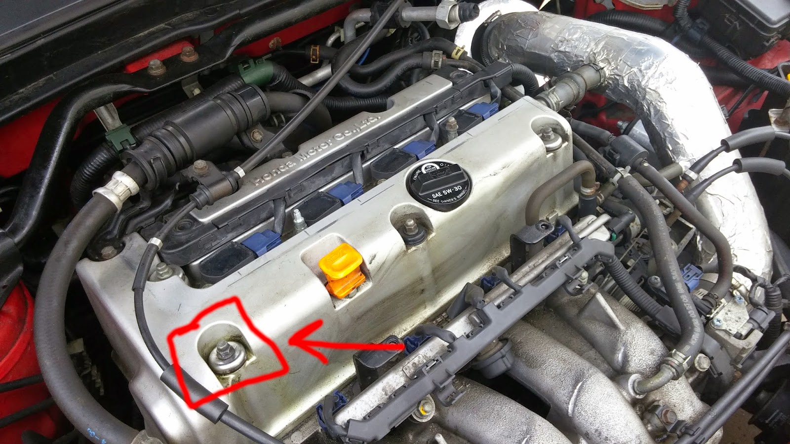
So, I simply took a bolt from somewhere else in the engine bay and replaced the one that fell off with it.  Notice how there's no washer on the middle, front valve cover bolt as well.  That's because I took that washer and used it on the corner valve cover bolt.

After that, for the second run I took things easy at first.  I watched my temperature gauge and looked in my rear view for smoke.  I also kept my senses keen to make sure that no funny smells were coming from my engine bay.  With all things in check, I began to push the car a little harder and I still did not get passed once.

Finally, before I started the last lap, I asked the novice instructor, Tom, about one corner in particular that I did not know how to handle.  It was unlike some of the kinks that took place at high speeds because for those I could just let off the throttle, oversteer, and hit the gas.  It was also unlike the low-speed technical corners where I could slam the brakes, oversteer, and hit the gas.  

He ended up telling me to keep the car in forth gear, brake gradually, and let off gradually.  Doing so induced corner entry oversteer and allowed me to power out of the corner.  Here's the corner I'm talking about:


If you want to take a look at my driving, check out this video!  It has a lot of comments to help you guys see what I was thinking and what I was doing to be slower or faster through given sections and corners!  Maybe if you want to get into track racing this will help you!


At the end of the day I ended up meeting a bunch of people and having an amazing time.  Everyone agreed that I was the fastest of the day and I learned so much and had a blast driving with the other novices.  People kept asking if my car was turbocharged and how much displacement I had.  When one driver heard I had an N/A 2.0 liter motor he was shocked!

When I was leaving, some instructors even stopped by and asked who was driving the "red Honda" as everyone called it.  They said, yeah, "you're definitely ready for intermediate group!"

It felt so good finally being fast-- as compared to autocross where all of the lighter cars with better tires destroy me.  I guess we'll see how I do next time!  But for now, I'm gonna sign off.  Hope you had fun reading!

Sunday, December 30, 2018

#ChelseaTheCivic, Part 2: Upgrading the Stock Honda Ignition System

Honda made some of the best cars from the late 80s to early 00s with double wishbone suspension, light-weight chassis, lots of cargo room, optional VTEC motors, and low price tags.  These aspects and other things contributed to the success of these cars on track and help explain why they are still so commonly seen at track day and road racing events in North America.

Figure 1: 2007 National Auto Sport Association (NASA) Championships

However, when subjecting any car to the stresses of track duty, weak points will be discovered.  

In our last post we discussed how to remedy commonly suffered axle problems in your B-Series Honda with proper maintenance.  In this post, we will discuss another problem common to late 80s through early 00s Hondas in general-- distributors, or in slang terms, "dizzies."

Figure 2: A Distributor on a Toyota (Ref)

If you only have owned newer cars, it's likely you haven't heard of a distributor before.  Maybe you have, but maybe you don't know how it works.  Well, let's go over some background info to ensure you understand the basics.

Simply put, the distributor is a collection of components that uses the rotating energy from the car's engine to time and deliver the spark for each cylinder in an engine.  For the purpose of this blog post, it's important to know the following components in a Honda distributor:

1.) The ignition control module (ICM or Igniter)
2.) The cylinder position (CYP) coil or sensor
3.) The ignition coil

Figure 3: Important Components of a Honda Distributor (Ref)

The cylinder position sensor detects the position of cylinder number 1 as a reference for fuel injection.  This is one of the sensors inside of a Honda distributor used to detect engine speed or cylinder position. (ref. 1, 2).

The ignition control module, or "igniter" shown in the picture above is a solid state device that takes the continuous signals from the aforementioned sensors and converts them into a digital signal (ref. 3).  This is similar to how a power inverter takes DC power from your car's battery and converts it to AC power for a typical 110V outlet.

Figure 4: A Continuous Electric Signal Vs. a Digital Signal (Ref)

While the digital signal from the ICM may be in-sync with each cylinder's stroke, the digital signal cannot make a spark inside of the cylinder since it doesn't have enough energy.  To increase the energy present in this signal, the ignition coil must be used.  The ignition coil takes the low voltage signal and amplifies it (ref 4).  This is similar to how pole-mounted step-down transformers take power from power lines and convert them to a usable voltage and current for your home.

Figure 5: Diagram of a Pole-Mounted Transformer (Ref)


This same high voltage signal reaches each cylinder to create the spark that completes the combustion triangle, which is a graphic representation of what's required to create combustion.  The spark is the heat, the air from your intake manifold supplies the oxygen, and the gasoline from your fuel injectors is the fuel.  The reaction that ensues generates pressure and makes the piston move down, forcing the crankshaft to spin around.

Figure 6: Combustion Triangle (Ref)

Now that we've explained some of the basics, we can delve into the fun part-- modifying the car. 

While at NJMP for my last race of the 2018 season, I experienced my first distributor failure.

I was leading a race when going around "the octopus" at New Jersey Motorsports Park's (NJMP) my car developed a serious misfire.  I turned the car off and on several times and toggled the kill switch, but to no avail.

Figure 7: Video of Second-to-Last Race of the Season Where Distributor Failed

When I got the car back into paddock, I pulled my distributor cap, since I knew that these dizzies are a common problem in these cars, and lo' and behold, I found an obliterated distributor rotor.  The cause?  The screw holding the rotor onto the distributor let loose due to vibrations.

Figure 8: Failed Distributor Caused by Loose Rotor Screw

For that weekend, I was able to compete in my second race by sourcing a spare rotor from a friend.  I was able to finish my season and secure 2nd out of 4 competitors while facing a large number of personal hardships during 2018, including missing my first race weekend.

Figure 9: Getting Ready for a Race at NJMP

Even with my failure occurring at the end of the season, I got lucky.  90s Honda distributors are notorious for failing in track-driven Hondas.  The two common failures are the ignition control modules and the ignition coils.  

Ignition coils and ICMs fail due to heat, vibration, and age.  So, if you can remove some heat and vibration, and replace the OEM component with a better, aftermarket component, you can increase your reliability.  So, I decided to do exactly that-- enter the MSD Blaster Coil SS.

Figure 10: The MSD External Blaster Coil Upgrade Kit (Coil is Red Object at Far Right)

You can order the entire MSD Blaster Coil kit from eBay for a little over $100 bucks or you can source all of the components you need like I did from friends and discounted sources.  The kit consists of:

1.) A modified distributor cap with a connection for the external ignition coil
2.) A new rotor
3.) A gasket for the new cap
4.) A common-place 7 mm spark plug wire used to connect the new cap to the external coil
5.) The external coil itself
6.) Mounting hardware for the external coil

To install the MSD unit, the distributor has to be opened up and some wires have to be cut and re-soldered.  A straightforward installation guide can be found here.

The installation isn't hard, but while I was inside of my distributor, I decided to inspect it for damage that may have been caused by the failure at NJMP.  I also wanted to replace the screw that holds the distributor rotor with a hex bolt.

Figure 11: Honda Distributor with Removed Ignition Coil, Rotor, and Cap

One of the first issues I identified when taking apart my distributor was that the wire leading to my CYP sensor was nicked in two places, one of which was too close to repair with the existing CYP unit.  While my distributor did fully function with these knicked wires, I didn't want to risk a subsequent failure by being lazy.  A failed CYP sensor can put the car into limp mode which would cause me to lose another race.

Figure 12: CYP Coil/Sensor with Damaged Wires

Normally when the CYP sensor is bad, the whole distributor housing has to be replaced, as these CYP sensors are not sold individually.  However, my friend Spencer gave me a spare distributor and MSD Blaster Coil Cap when I experienced my failure at NJMP.  Since his distributor was OBD2 and mine is OBD1, I couldn't use his housing outright, but I could take the CYP sensor from his donated unit and use it on mine.

So, with no further delay, I began surgery.

Figure 13: Spencer's CYP Coil Being Installed on my Distributor

Figure 14: One Wire Soldered and Heat-Shrinked with The Second Wire Soldered, Awaiting Heat Shrink

With the CYP coil fixed, I began cutting and soldering wires as described on this website.

Figure 15: Picture from ImportNut.Net Showing Cutting and Soldering of Dizzy Wires (Ref)

After buttoning up the wires to connect the external coil and routing them outside of the distributor, I began reassembling the distributor.  As mentioned above, I wanted to replace the screw that holds the rotor on the distributor shaft with a hex bolt.

I wanted to do this because rotor screws have a habit of backing out on these distributors unless you blue Loctite the threads.  Once you do use blue Loctite, it is very difficult to remove the screw at a later point.  To remove my screw which was secured with Loctite, I had to use an impact flat head screw bit and a drill.

Figure 16: Rotor Screw Carnage Due to Blue Loctite

The hex head of the new bolt fastener will allow for more torque to be applied since it has more "meat" than a Phillips head screw.  In theory this will allow me to avoid using blue loctite to secure the rotor.

The only bolt I had that matched the diameter and pitch of the distributor rotor screw was an interior bolt from an Integra.  This bolt was longer than the rotor screw, which is great for my needs.  However, this is a specialty bolt with a wide diameter washer fixed to it.  So firstly, the washer would need to be cut off.


Secondly, the head of the hex bolt is too high and does not clear the plastic shroud inside of the distributor. 


Under operation, this would wear a hole in the plastic shroud and fill the distributor with debris.  To fix this, I ground the top of the hex bolt down.  Even with the bolt ground down, the socket still had enough bite to tighten the fastener, AND the bolt has a Phillips head if the hex head strips.


With the rotor attached to the distributor shaft, the plastic shroud in place, and the wiring for the external coil complete, I put the aftermarket MSD cap, which I sourced from Spencer's spare distributor, onto MY distributor and mounted it to my engine.


With the distributor installed, the next step is to mount the external coil and connect it to the distributor.  To start, I wanted to keep the wires from the distributor to the coil safe from heat and vibrations.  To do this, I routed the wires upward, away from the coolant hoses, heat shrinked the wires, then added a stress relief loop.


Next I began working on a mount for the external coil.  I knew I wanted to mount the coil in the empty space where my air box used to be.  I plan on building a divider wall to insulate this area from heat and routing my intake there anyway, so I figured this would be nice and cool and far away from engine vibrations.  However, I didn't have anything to mount to the external coil to.

I began scrounging for scrap metal.  Under my work bench I had a steel oil pan from a K24A1 that wouldn't sell on eBay for more than $10, if that.  So, I decided to use the metal from this oil pan to create a mount.


You'll notice the oil pan has an oval-shaped extrusion for where the oil pump pickup goes on the K24A1.  I decided to cut out this section.  My goal was to mount the external coil to this extrusion since I figured it would add rigidity to the mounting location-- again, reducing vibrations.

With that said, I began cutting so I could fit it up against the shock tower.  The goal was to have one side of the bracket mount to an OEM location on the shock tower and then one side of the bracket mount to an OEM location on the frame rail.  However, as you can see below, I came up short with the material I had.


However, with a welder, anything is possible.  So I cut out some more metal, mocked it up in my vice, and welded it together.


To get the bracket to mount to the frame rail, I bent it in my vice, marked where to drill my holes, and then mocked it up with some spare hardware I had laying around (likely from an Integra or Civic).  Below you will see how I installed the bracket and where I wanted my external coil to sit.


With the location set, I then painted the bracket to prevent rust from setting in and, of course, because it looks awesome.


Finally, I drilled the mounting holes for my external coil and bolted everything into place.


The next step was to connect the wires from the distributor to the coil.


Instead of utilizing the provided crimp-style connectors, I opted to remove the plastic sleeves from the ring terminals, crimp the ring terminals onto the wires, solder the ring terminals to the wires, and heat shrink all of it together.  In the long run, this will provide more reliability as the wires will be sturdier.  The process is simple.

1.) Insert the stripped wire into the ring terminal


2.) Crimp the ring terminal onto the wire


3.) Solder the ring terminal to the wire


4.) Apply heat shrink over the soldered connection


Finally, I routed the wires through a bracket for the engine harness to keep the engine bay clean, and connected the wires to my external coil.


All that remains for my upgraded ignition system is to connect the large terminal from the coil to the large terminal on the aftermarket cap.  Currently I'm waiting on the wire to make that happen.


Thank you all for reading.